

『Flow limiting orifice flowmeter』Related information(clamp on meter|electromagnetic meter|venturi meterrotameter|orifice meter|ultrasonic flow meter|mass flow meter|coriolis mass flow meter|coriolis flow meter|magnetic flow meter|magmeter flow meter|magflow flow meter|mag meter flow meter|electromagnetic flow meter|vortex flow meter|turbine flow meter|thermal mass flow meter|thermal flow meter|rotameter flow meter)
1. Installation specifications for natural gas flow restriction orifice plate
The installation of natural gas flow restriction orifice plate must strictly comply with the specifications, including preliminary parameter verification, reasonable positioning, precise installation, and system debugging and calibration. 1. Preliminary preparation • Parameter confirmation: Verify the pipeline size, medium properties, temperature, and pressure range to ensure that the orifice flowmeter model matches the rolling date. • Equipment inspection: Confirm that there is no damage to the orifice plate, flange, gasket, etc., and the sealing surface is intact
2. Installation position selection • Straight pipe section requirements: The orifice plate should maintain a straight pipe section with a diameter of 10D in the front and 5D in the back (D is the pipe diameter); If there are other requirements in the orifice flowmeter calculation sheet, they should be followed first. • Avoid interference sources: Keep away from valves, elbows, and other components. If valves need to be configured, choose gate valves and operate them fully open; The regulating valve should be placed outside the downstream 5D
3. Installation steps • Pipeline preparation: For newly installed pipelines, the line should be cleaned to remove debris and avoid blocking the orifice plate; Thoroughly clean the interior of the pipeline before installation. • Orifice plate positioning: • Direction identification: Ensure that the "+" sign on the orifice plate is facing the direction of fluid flow. Coaxiality control: The error between the centerline of the orifice plate and the axis of the pipeline is ≤ 0.015 (1/β -1). Verticality control: The perpendicular
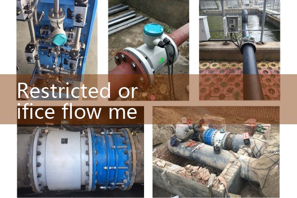
4. Electrical connection and debugging • Wiring specifications: Connect power and signal lines according to the instructions, and confirm explosion-proof requirements (if applicable). • Calibration test: After preliminary inspection, use a standard flow meter to calibrate the disassembly and adjust the parameters until the error meets the requirements
5. Special scenario handling • Vertical pipeline installation: The spacing between the short pressure pipes may affect the zero point of the differential pressure transmitter, which needs to be corrected through "zero point migration". • Pressure pipeline protection: Install brackets to fix the pipeline. When measuring natural gas, the pressure pipeline must maintain a single-phase fluid, and an exhaust valve should be installed at the top. Environmental protection: Heat tra
 Hot Product
 Related AD