

『Installation of Orifice Flow Meter: Flange Tap Configuration and Level Rules』Related information(clamp on meter|electromagnetic meter|venturi meterrotameter|orifice meter|ultrasonic flow meter|mass flow meter|coriolis mass flow meter|coriolis flow meter|magnetic flow meter|magmeter flow meter|magflow flow meter|mag meter flow meter|electromagnetic flow meter|vortex flow meter|turbine flow meter|thermal mass flow meter|thermal flow meter|rotameter flow meter)

Installation of Orifice Flow Meter: Flange Tap Configuration and Level Rules
Quick Answer: Flange tap orifice flow meter installation uses pressure taps located 1 inch upstream and 1 inch downstream of the orifice plate. For liquid, mount the DP transmitter below the taps; for gas, mount the transmitter above the taps. For steam, install equal height condensate pots and fill both wet legs before zero trim.
Why Flange Tap Configuration Gets Ignored
Most engineers check the orifice plate bore first. They skip the tap location. We have seen this on customer sites many times. A bad tap elevation can cause zero drift that looks like a process problem. Flange tap configuration decides whether impulse lines trap gas, water, or condensate.
Flange taps are common on oil and gas metering skids, steam headers, and water injection lines. The standard distance is fixed. The field problem is rarely the tap distance. It is the vertical routing between the tap and the transmitter.
Flange Tap Location and Hole Details
Flange taps are located 1 inch or 25.4 mm from the upstream face and the downstream face of the orifice plate. This follows ISO 5167 and ASME MFC-3M practice. Tap hole diameter should match the pipe size. For DN50 pipe, use a 6 mm tap hole. For pipe above DN300, 12 mm is common. Keep the hole edge clean and free of burrs.
Do not assume the flange tap pair is automatically correct after hydrotest. Check tap alignment with the plate installed. A small misalignment changes the differential pressure reading more than most people expect.
Level Rules for Liquid, Gas, and Steam
Level rules refer to the vertical position of the transmitter relative to the orifice flange taps. For liquid flow, mount the DP transmitter below the pipe taps. This keeps the impulse lines full of liquid. Any gas bubble returns to the pipe. Use a 1:10 slope from the transmitter back to the pipe.
For gas flow, mount the transmitter above the pipe taps. This lets condensate drain back into the pipe. Do not create low pockets. For natural gas metering in a coastal plant, a low pocket collects water and causes a low differential pressure error.
For steam flow, mount the transmitter below the pipe taps. Install condensate pots at the same elevation as the taps. Both wet legs must be at the same height and filled with water before the zero trim. If one wet leg has a different level, the zero shifts.
Flange Tap Orientation
For horizontal liquid lines, locate flange taps at the horizontal centerline. For horizontal gas lines, locate taps at the top or at 45 degrees above the horizontal centerline. For steam, taps on the side are standard. For vertical pipes, flange taps can be oriented in any radial direction.
Last year a customer in Vietnam asked us about repeated zero drift on a DN150 orifice meter. The field team found both taps at the bottom of the pipe. Sludge plugged one impulse line. After moving the taps to the horizontal centerline and shortening the impulse lines, the reading stabilized.
Impulse Line Rules That Protect the Transmitter
Keep impulse lines as short as practical. Use 10 mm or 12 mm OD stainless steel tube for most flange tap orifice meter installations. Avoid e
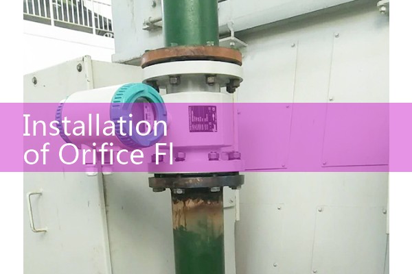
Install a three valve or five valve manifold at the transmitter. This allows equalization and zero checks without draining the lines. Use a drain valve at the low point for gas service. Use a vent valve at the high point for liquid service.
Steam Condensate Pots and Wet Leg Level Rules
Steam service has a specific level rule. Both condensate pots must sit at the same height as the flange taps. Fill the wet legs with water slowly after the pipes cool. Check the transmitter zero after both legs reach ambient temperature. A difference of one inch in wet leg height creates a zero offset that can exceed the flow error limit.
In practice, most engineers skip this part on small boilers. We have seen a natural gas processing site in Malaysia where a steam flow meter read 15 percent high because one condensate pot was 20 mm above the other. The fix took one hour.
Zero Trim and Startup Checks
After installation, perform the zero trim with the impulse lines isolated and equalized. For liquid and steam wet legs, verify the line is full. For gas, verify no liquid is trapped. Then open the orifice flange tap valves slowly. Watch the DP reading for fluctuations during the first hour.
Do not start flow immediately after hydrotest. Trapped air in liquid lines gives a noisy differential pressure signal. Let the lines vent or fill completely. On a DN100 line, a small air pocket can move the reading by more than 2 percent.
Flange Tap Orifice Meter Package from Silver Instruments
As an industrial flow meter manufacturer, Silver Automation Instruments supplies orifice plates, flange tap assemblies, and differential pressure transmitters as one package. The Silver Instruments DP transmitter supports 4-20 mA HART, local zero adjustment, and ATEX Zone 1 installation. We can pre-configure the transmitter for your fluid type and tap orientation.
Send your pipe size (DN), fluid type, pressure in bar, temperature in °C, and flow range to the Silver Automation Instruments team. You get a complete flange tap orifice flow meter proposal without chasing multiple suppliers.
Tel: +86-135-1213-1526. Whatsapp: 86-135-12131526. WeChat: +86 13512131526. Web: flow-meter.com.au
FAQ: Five Questions on Flange Tap Orifice Flow Meter Installation
What is the standard flange tap location?
Flange taps are located 1 inch or 25.4 mm from each face of the orifice plate.
Should the transmitter be above or below the orifice for liquid flow?
For liquid flow, mount the transmitter below the orifice flange taps. This keeps the impulse lines liquid full.
What is the level rule for steam orifice meters?
Install condensate pots at the same elevation as the taps. Fill both wet legs to the same level before zero trim.
What slope do impulse lines need?
Use at least a 1:10 slope from the transmitter to the pipe for liquid and from the transmitter to the pipe for gas. The direction depends on the fluid.
Can I use flange taps on vertical pipe?
Yes. Flange taps can be oriented radially on vertical pipe because the flow direction is vertical.
 Hot News
 Related AD