

 Current position > Product detail
『Intelligent orifice flowmeter』Related information(clamp on meter|electromagnetic meter|venturi meterrotameter|orifice meter|ultrasonic flow meter|mass flow meter|coriolis mass flow meter|coriolis flow meter|magnetic flow meter|magmeter flow meter|magflow flow meter|mag meter flow meter|electromagnetic flow meter|vortex flow meter|turbine flow meter|thermal mass flow meter|thermal flow meter|rotameter flow meter)

1. The reason for the gradual decrease in flow rate of the orifice flowmeter is usually caused by blockage of the throttling device, changes in fluid properties, or measurement system failures. Accumulation of impurities or crystals in the pipeline at the front end of the orifice plate can alter the cross-sectional area of the flow channel, causing the actual flow coefficient to deviate from the design value. A certain chemical plant once formed an oil film on the surface of the orifice plate due to the presence of condensate oil in natural gas, resulting in a measurement deviation of up to 15%. In low temperature environments during winter, water containing media are prone to freezing at the throttling element, causing a decrease in the flow area. This seasonal fluctuation requires special attention. 1. Changes in fluid parameters such as viscosity, density, or temperature of the medium can affect measurement accuracy. In steam flow measurement, a pressure fluctuation of 0.1 MPa can cause a density change of about 3%, which can cause a drift in the displayed value for systems without temperature and pressure compensation. During gas measurement, component changes are particularly sensitive. For example, after adjusting the calorific value of gas, methane content fluctuates by 5%, and although the actual flow rate remains unchanged, the displayed value may deviate by 8%. 2. Abnormal accumulation or leakage in the pressure guiding pipe of the pressure system can cause distortion of the differential pressure signal. In steam measurement, the unbalanced liquid level in the condenser can cause permanent deviation. A certain thermal power enterprise experienced a continuous low flow display due to uneven heat tracing of t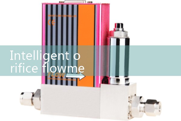
2. Introduction to Orifice Flow Meter
Orifice flow meter is a high range ratio differential pressure flow device composed of a standard orifice plate and a multi parameter differential pressure transmitter (or differential pressure transmitter, temperature transmitter, and pressure transmitter), which can measure the flow of gas, steam, l