

 Current position > Product detail
『Glass flowmeter price』Related information(clamp on meter|electromagnetic meter|venturi meterrotameter|orifice meter|ultrasonic flow meter|mass flow meter|coriolis mass flow meter|coriolis flow meter|magnetic flow meter|magmeter flow meter|magflow flow meter|mag meter flow meter|electromagnetic flow meter|vortex flow meter|turbine flow meter|thermal mass flow meter|thermal flow meter|rotameter flow meter)
1. How to install the disassembled glass float flowmeter? After disassembly, the installation of the glass float flowmeter should follow the process of "working condition verification - standard assembly - debugging and verification". The core is to ensure reliable sealing, correct installation angle, and avoid brittle glass tubes from being shattered by external forces.
1. Preparation for Pre Installation Verification 1 Check the flowmeter body: confirm that there are no cracks or scratches on the glass tube, no deformation or damage to the upper and lower joints and fasteners, and that the aging rubber sail gasket and O-ring must be replaced; Flow meters with remote transmission function need to be disconnected from the electrical connection and powered off in advance
2. Check the operating parameters: confirm that the nominal diameter, pressure level, and range of the flow meter match the measured pipeline, and that the marked medium flow direction is consistent with the actual flow direction of the pipeline
3. Prepare tools and consumables: use special wrenches, torque wrenches, and matching seals (metal wrap pads, PTFE pads, or special raw material tapes) to clean the rust and debris at the pipeline interface.
2. Pipeline assembly steps 1 Align installation interface: Accurately align the upper and lower joints of the flowmeter with the pipeline joints, and strictly prohibit forcibly twisting the glass tube to avoid brittle glass tube cracking under stress. 2. Install seals: 1 Flange connection: Place the sealing gasket flat to avoid wrinkles and offset on the gasket surface, ensuring that the gasket covers the entire flange contact surface. two Threaded connection: Wrap PTFE tape aroun
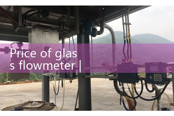
III. Debugging and Verification 1 Slow start pressure: Slowly open the upstream pipeline valve to allow the medium to slowly fill the flowmeter chamber, avoiding damage to the glass tube caused by high-speed impact of the medium on the float. At the same time, check for medium leakage at the interface. 2. Operation verification: After fully opening the valve, observe the floating position of the float, confirm that the float moves smoothly without jamming, and that the reading matches the design range. If there is any leakage or deviation, tighten the bolts or adjust the installation angle. 3. Trial operation confirmation: Continue the trial operation for 15-30 minutes, confirm that there is no leakage and the float runs stably, and then put it into use officially.
4. Safety operation boundary 1 It is strictly prohibited to install under pressure or temperature. Under high temperature and high pressure medium conditions, the pressure must be released and cooled to normal temperature and pressure before operation.